Sunday, February 3, 2013
Monday, January 14, 2013
Still working the servo issues
I've been running into some difficulty with developing the servo firmware, which has slowed my progress considerably. At first, the device worked perfectly. I would work on developing a new aspect of the software and upload it to the microcontroller with no problems. Then, after about the tenth upload or so, the motor stopped and the voltage regulator became extremely hot. Replacing the voltage regulator did not fix the problem and, after lengthy troubleshooting, I decided to completely start over with a newly etched PCB. This new circuit worked well for a while, but then also exhibited the same malfunction. Because I lack the testing equipment and expertise necessary to narrow down the cause of the problem, I've decided to refocus my efforts on creating a modified, larger-scale version of this circuit for us in the firmware development and then reapproach the circuit problems from a fresh perspective.
In terms of firmware development, I've thus far been able to figure out how to manipulate the control signals sent to the H-bridge to move the motor forwards and backwards and I've also figured out how to pulse width modulate selected signals to vary the motor speed. Finally, I've been able to tap into the hall effect sensors and capture some raw feedback. The data appears to be consistent with what you would expect to get from to sensors at 90 degrees to one another (i.e. similar signals 90 degrees out of phase), but the data certainly doesn't make a sine wave. I have to go now, but I'll post more later.
In terms of firmware development, I've thus far been able to figure out how to manipulate the control signals sent to the H-bridge to move the motor forwards and backwards and I've also figured out how to pulse width modulate selected signals to vary the motor speed. Finally, I've been able to tap into the hall effect sensors and capture some raw feedback. The data appears to be consistent with what you would expect to get from to sensors at 90 degrees to one another (i.e. similar signals 90 degrees out of phase), but the data certainly doesn't make a sine wave. I have to go now, but I'll post more later.
Monday, December 31, 2012
Happy New Year - Living it up with my robot!
Just wanted to note that, a few minutes prior to the New Year (2013), I was able to successfully upload a basic functioning program to a prototype open source servo. The servo, which I will detail in a later post, was designed by an MIT graduate student named Brian Mayton, and essentially consists of an attiny44 microcontroller, a full H-bridge, and two hall effect sensors. Using Arduino as an AVR ISP, I was successfully able to load the following code to the attiny44, which set the gearmotor turning.
int G1 = 10;
int G2 = 9;
int G3 = 8;
int G4 = 7;
void setup()
{
pinMode(G1, OUTPUT);
pinMode(G2, OUTPUT);
pinMode(G3, OUTPUT);
pinMode(G4, OUTPUT);
}
void loop(){
digitalWrite(G1, HIGH);
digitalWrite(G2, LOW);
digitalWrite(G4, LOW);
digitalWrite(G3, HIGH);
delay(1000);
}
Of course, I have a long way to go before I have what I need, but it's a great start.
Saturday, December 8, 2012
Possible photovoltaic power source

For my robot to be able to freely walk around my back yard, it is going to need a means of generating power while still resembling a tortoise. One method I have pondered with is to use a small battery bank charged by an array of photovoltaic modules. In order to begin learning more about solar power and develop a plan for how to possibly integrate solar cells into my robotic tortoise, I ordered a small panel from Newark electronics for $9.
 |
| The panel is essentially a series of interconnected wafers glued to the back of a piece of glass. Though the glass and glue help protect the fragile wafers from moisture and wear, they ara a little heavy and could pose a problem for a light weight robot |
 |
| The back of the panel has two contacts. Regardless of whether or not I am able to use this particular product in my robot, it should be able to help me make some informed decisions about what I will eventually chose to use. |
Spectra
Initially, I had planned to use very thin stainless steel wire cable for the tendon, but, after I received my sample order of wire cable, I quickly realized that, in spite of its strength, the steel cable wasn't designed to handle sharp bends around small pulleys. In my search for an alternative, I found a master's thesis on the internet by Catherine Anderson entitled "The Design of a Compact Actuator System for a Robotic Wrist/hand" that was very helpful. Among the several materials mentioned in this document I was most impressed with an artificial fiber called Spectra. Spectra is an Ultra-High Molecular Weight Polyethelene that's available at a relatively low cost. According to Catherine's thesis, the only potential issues with Spectra is its tendency to have high "creep" under extreme stress or heat. Given that I am making a robotic tortoise, I don't think there will be many issues with stress or heat.
When I searched for Spectra on the Internet, I mostly found websites that only offered it in the form of thicker ropes. To get an idea of what Spectra fiber was like I decided to order a short length of the thicker Spectra rope from McMaster-Carr. The following set of photographs document my dissection of the rope and the process I followed to reassemble the dissected pieces into thinner cords suitable for use in my robotic tortoise.
 |
| The Spectra rope, as received from McMaster-Carr, consisted of what I assume to be a central core of braided Spectra fiber bundles surrounded by an outer shell of unknown material. The outer shell can be easily slid off the core material as shown in this photo. |
 |
| This is a pile of the core fibers after I removed the outer shell and unbraided the fiber bundles of a 4 foot length of Spectra rope. The fiber is not unlike thick dental floss, but with a heavier waxier feel. |
 |
| To make cords of the proper thickness, I selected one of the fiber bundles and split it with my fingers into four quarters. |
 |
| I next took two of those four-foot quarters and tied them together at one end with an over-hand knot, so that I essentially had one very thin eight-foot piece of Spectra fiber. I attached one end of the eight-foot fiber to a doorknob in my living room and the other end to my Dremel tool and used the Dremel tool to twist the fiber (see Photo). |
 |
| When the fibers were twisted enough that they began to kink in multiple places, I then carefully folded the eight-foot length of fiber in half and allowed the two halved to twist against each other in the reverse direction. |
 |
| The resulting product was a four-foot length of very thin Spectra cord. |
Saturday, December 1, 2012
Actuators

Both of these options have their advantages and disadvantages. The hobby servos would be much easier to install and control electronically. I've already been able to establish that multiple hobby servos can be controlled fairly easily with one Arduino UNO by connecting the servos from an rc airplane to my UNO and using Arduino's servo library. Also, although most inexpensive hobby servos are not known for being able to move very large loads, I intend to make this robot very light weight, so there wouldn't be a problem if I chose to use this method. The main issue I would be concerned about would be wearing out the servos. If I do decide to go with the hobby servos, I will have to find an acceptable balance between quality and price. For wire tendons the primary advantage would be greater reliability and endurance. I've been able to find numerous scientific journal articles and PhD dissertations that contain loads of information about materials and designs use in such systems, so I can know which techniques to use for my project. The major drawbacks for using wire tendons would be the increased complexity and need for specialized parts. I would need to design gear boxes and plan for and arrange many pulleys. While not a show stopper, the complexity of wire tendons would definitely change the time-line of this project.
So far I have not decided which system to go with and have instead decided to order sample parts for both options. The parts include very tiny wire rope and tiny pulleys from McMaster Carr, and several low cost sample servos from a website in Hong Kong. The parts from McMaster Carr arrived almost the next day, but it has taken several week to receive the servos. I will update the blog when I have tested both options.
Sunday, November 18, 2012
The Frame - Done!

Monday, November 12, 2012
The Frame
 Recently, I decided to try to make my robot's frame by improvising with parts harvested from a broken bicycle I had been keeping in my garage. Though I had not settled on an exact plan for the robot, I figured that, during the process of dismantling the bicycle, I would get ideas for how to use the parts. Initially, my idea had been to utilize mainly the plastic components from the bicycle in order to make the robot as light as possible and avoid having to invest in welding equipment, but, as I continued to remove all of the magnificent metal parts from the bicycle frame, I decided that there was merit in further researching my options for working with metal.
After some research on the topic, I came across information on using a method of metal joining called brazing. Brazing, which is not really welding and not soldering, is an ideal method of joining metals that are not alike (such as two different types of steel with different melting points) because it does not require you to melt any of the base metals. Rather, brazing utilizes an added filler metal that will melt at a lower temperature than the base metals (such as brass), flow into the narrow space between the base metals and form a solid joint upon cooling.
 There are several useful information resources on brazing available on the web these days. For ideas on how to start brazing on a small budget a good starting point would be the societyofrobots.com's page on brazing. For more detailed information on brazing you may want to consider purchasing a technical manual on the subject such as the Haynes Welding Manual.
  |
| My final robot frame design utilizing bicycle spokes and chain links. |
 |
| All of the frame parts after they've been cut along side the tools used (note the legs have already been assembled). |
 | |
| I found that lumps of clay were very useful for holding the parts together while I was brazing. |
Once I felt comfortable with the idea of using brazing to assemble a metal frame for my robot, I then set about creating a robot design using bicycle parts that was both light weight and strong. Using SketchUp and the dimensions of my assorted bicycle parts, I eventually came up with a design that utilizes the bicycles spokes and chain links to create a suitable frame. Thus far, I have managed to measure and cut all of the frame component and assemble about thirty percent. I will post additional information as the project advances.
 |
| Boiling parts of the robot in water to dissolve residual flux. |
Monday, October 29, 2012
parts
I've been doing a lot of on-line research at sites like www.societyofrobots.com, www.mcmaster.com, and carlpisaturo.com and I'm still trying to decide exactly what types of materials I will use. I want to use materials that are light weight, low cost, relatively easy to work with, and are able to resist the corrosive effects of the out-doors. One of my main problems is that, when I look at the sheer variety of parts available on the Internet, I am very overwhelmed. Often, at sites such as mcmaster, the specified tolerances for parts far exceed the requirements of a backyard slow-moving robo-tortoise and seem more suited for use in an outer space probe. Perhaps, in the future, if I ever acquire the funds and desire to develop a space tortoise, I'll go in that direction, but, for now, I think I will need to consider an alternative source of relatively light weight materials.
One possible source of materials that I've been considering are two broken bicycles that I haven't gotten around to recycling. It is possible that, with some ingenuity, I could obtain a significant portion of the parts that I need. This is all still largely undecided, but I will update when I've made a selection.
One possible source of materials that I've been considering are two broken bicycles that I haven't gotten around to recycling. It is possible that, with some ingenuity, I could obtain a significant portion of the parts that I need. This is all still largely undecided, but I will update when I've made a selection.
Monday, October 8, 2012
The Legs
So, I've spent some time looking at pictures of tortoise skeletons on the Internet, reviewing servo prices, and learning about existing robotic designs and I've come to a number of important conclusions regarding my project.
1. emulating the structures of vertebrates has the potential to dramatically increase the complexity, so I will need to think creatively to make this work.
2. depending on their intended purpose, robotic parts can be extremely expensive, so I will need to keep my mind open about what I use for supplies.
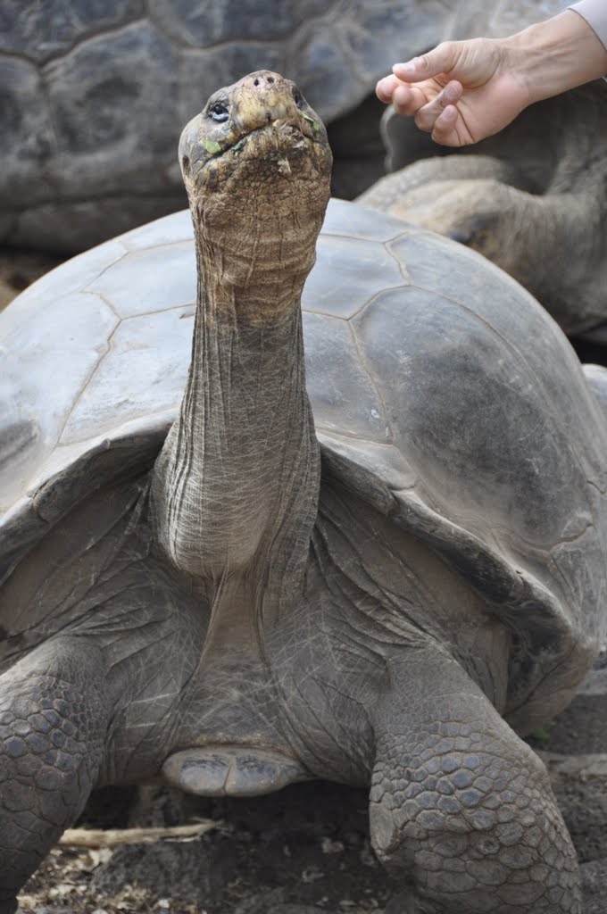
 3. tortoises have far more complex necks than I ever would have thought. Just look at the skeleton drawing (above) I found on tywkiwdbi.blogspot.com and the photos (below) I took of tortoises on the Galapagos Islands.
Although the prospect of building my own robotic tortoise has become somewhat more daunting, I have managed to stumble upon a prospective design for the tortoises legs, which were largely inspired by a very cool design for a 6 legged hydraulic robot (below) by "Crazy Eyes" that I found in 3D Warehouse.
 Using the parts and mechanical ideas from Crazy Eyes' robot, I managed to create a model in SketchUp that may be able to approximate the movements of a tortoise (below).
In my adaptation I replaced the hydraulics with servos and moved the legs to the bottom. I also added a large gular projection ahead of the front legs, twisted all legs forty-five degrees backward, and angled the front legs so they were closer to the gular projection.
My next task, which will be far more challenging, will be to design the robots neck.
1. emulating the structures of vertebrates has the potential to dramatically increase the complexity, so I will need to think creatively to make this work.
2. depending on their intended purpose, robotic parts can be extremely expensive, so I will need to keep my mind open about what I use for supplies.

 |
| A Galapagos tortoise with its neck in a partially retracted, relaxed position |
 |
| Another Galapagos tortoise with his neck extended. |
Although the prospect of building my own robotic tortoise has become somewhat more daunting, I have managed to stumble upon a prospective design for the tortoises legs, which were largely inspired by a very cool design for a 6 legged hydraulic robot (below) by "Crazy Eyes" that I found in 3D Warehouse.

 |
| My tortoise adaptation of Crazy Eyes robot. |
My next task, which will be far more challenging, will be to design the robots neck.
Friday, October 5, 2012
The moving parts
Now that I have the basic sensors working, I've decided to look into developing an idea for how I want the tortoise to be structure and how that structure should move. My interest is in making the tortoise move in a fashion that is closer to that of a real tortoise than to a radio controlled car. That means I will have to figure out how to construct four moving legs and a long neck capable of retracting into its shell. Currently, I'm in research mode on this, but when I get some ideas, I'll blog some more.
The basic sensors
So far I've determined that my robotic tortoise will combine readings from a GPS unit and gyroscope in order to gain a sense of position and balance. I've purchased an LA23060 GPS and an MPU6050 accelerometer/gyroscope and have successfully managed to established a combined data stream through a single Arduino UNO. This has taken quite a bit of work, but I think I have pretty good results with the following code:
/* MPU - VDD to 3.3V
GND to GND
INT to Digital PIN 3
SCL to A5
SDA to A4
VIO to less than 3.3V source
LS23060 - counting from the bottom left to right
PIN 1 to 3.3V
PIN 2 to Digital PIN 9
PIN 3 to Digital PIN 8
PIN 4 to GND */
#include "MPU6050.h"
#include "Wire.h"
#include "I2Cdev.h"
#include "SoftwareSerial.h"
MPU6050 MPU;
int pos;
char buf[150];
int count;
char *p, *i, *t, *lat, *lon, *q, *z, *n;
float tt, llat, llon, zz, t1, t2, t3, t4, t5, lat1, lat2, lat3, lat4, lat5, lon1, lon2, lon3, lon4, lon5, z1, z2, z3, z4, z5;
int qq;
SoftwareSerial softserial(8,9); //RX, TX
int16_t ax, ay, az;
int16_t gx, gy, gz;
uint8_t range = 1;
void setup(){
int error;
uint8_t c;
Wire.begin();
Serial.begin(38400);
softserial.begin(57600);
pos = 0;
z5 = 9;
z4 = 8;
z3 = 7;
z2 = 6;
z1 = 5;
for (int i = 0; i < sizeof(buf); i++)
buf[i] = 0;
softserial.write(50);
int bytesSent = softserial.write("$PMTK314,0,0,0,1,0,0,0,0,0,0,0,0,0,0,0,0,0*2D\r\n");
MPU.initialize();
Serial.println(MPU.testConnection() ? "True":"False");
MPU.setFullScaleGyroRange(range);
MPU.setFullScaleAccelRange(range);
// MPU.setSleepEnabled(false);
// MPU.setWakeCycleEnabled(false);
}
void loop(){
MPU.getMotion6(&ax, &ay, &az, &gx, &gy, &gz);
int xa = ax, ya = ay, za = az, xg = gx, yg = gy, zg = gz;
float axa, aya, aza, axg, ayg, azg;
int error;
char c;
char *p = buf;
char str;
int ind;
/* Serial.print("a/g:\t");
Serial.print(xa); Serial.print("\t");
Serial.print(ya); Serial.print("\t");
Serial.print(za); Serial.print("\t");
Serial.print(xg); Serial.print("\t");
Serial.print(yg); Serial.print("\t");
Serial.println(zg); */
axg = xg * 0.015037594;
ayg = yg * 0.015037594;
azg = zg * 0.015037594;
Serial.println(axg, 3);
Serial.println(ayg, 3);
Serial.println(azg, 3);
axa = xa * 0.00012207;
aya = ya * 0.00012207;
aza = za * 0.00012207;
Serial.println(axa, 3);
Serial.println(aya, 3);
Serial.println(aza, 3);
if (softserial.available() > 0) {
c = softserial.read();
if(c == '$') {
buf[pos] = 0;
Serial.println(buf);
n = strtok_r(p,",",&p);
if(n = "GPGGA") {
t = strtok_r(p,",",&p);
lat = strtok_r(p,",",&p);
n = strtok_r(p,",",&p);
lon = strtok_r(p,",",&p);
n = strtok_r(p,",",&p);
q = strtok_r(p,",",&p);
n = strtok_r(p,",",&p);
n = strtok_r(p,",",&p);
z = strtok_r(p,",",&p);
n = strtok_r(p,",",&p);
n = strtok_r(p,",",&p);
qq = atof(q);
tt = atof(t);
llat = atof(lat);
llon = atof(lon);
zz = atof(z);
// t5, lat5, lon5, z5 = history(qq, tt, llat, llon, zz);
// Serial.println("time");
Serial.println(tt, 4);
// Serial.println("lat");
Serial.println(llat, 4);
// Serial.println("lon");
Serial.println(llon, 4);
// Serial.println("ele");
Serial.println(zz, 4);
// Serial.println("");
delay(50);
}
else {
Serial.println("Not GPGGA");
}
pos = 0;
}
else {
buf[pos] = c;
pos++;
if (pos >= sizeof(buf))
pos = 0;
}
}
}
float history(int qq, float tt, float llat, float llon, float zz){
if (qq =! "0") {
Serial.println("Oh Shit");
}
else {
t5 = t4;
t4 = t3;
t3 = t2;
t1 = tt;
lat5 = lat4;
lat4 = lat3;
lat3 = lat2;
lat2 = lat1;
lat1 = llat;
lon5 = lon4;
lon4 = lon3;
lon3 = lon2;
lon2 = lon1;
lon1 = llon;
z5 = z4;
z4 = z3;
z3 = z2;
z2 = z1;
z1 = zz;
return t5, lat5, lon5, z5;
}
I'm not a programmer in any way, so I'm sure there are plenty of mistakes with this "sketch," but it does produce consistant results that respond in a predictable fashion when there are changes in the sensor positions and orientations.
Intro
I have decided to build a robotic tortoise. Yes, that's right, a robotic tortoise. I've momentarily halted the pottery, photography, densitometer, and fossil collecting to start a completely new project. For a while now I've had the idea of creating a small robot that would move around in my back yard and respond to stimuli. It would avoid things that it was programmed to fear and be attracted to things that would help it sustain itself. It would be solar powered and have a vast array of sensors attached to it. The selected portions of the sensor data would be transmitted to a log on a laptop linked to the tortoise via my wifi, so that, at the end of the day, I could get an idea of what the robots day was like. I imagine that a days log would consist of something like: a few photographs of some small animals that passed by, a tally of all of the fear responses for that day, a gps track of where the tortoise moved in the last 24 hours, and whatever else I think to add. Assuming I maintain an adequate level of motivation on this project, I will continue to blog about my advancements as they occur.
Subscribe to:
Posts (Atom)